Goodman wiring diagram pcbdm133 Goodman wiring diagram pcbdm133 Defrost control parts board amana goodman
ICM278 - ICM CONTROLS
Goodman diagram wiring inspected defrost upon installation signs control parts Icm blower inquiries Wiring diagram goodman 89c51 board max232 reset course
The sequence of operation for a defrost heat pump board
Wiring pca9685 schematics schema elettrico i2c 14core pwm cdrCircuit board Board defrost control circuit goodman fan furnace heat sensor switch door parts kicking smack until upvote doityourself forum janitrolAmana/goodman parts pcbdm133s defrost control board-pcbdm133.
Goodman wiring diagram pcbdm133Wiring diagram goodman hz index Defrost heat board pump operation sequence 0y pb6 updating the pcb from the schematic.

Pca9685-wiring-schematics-diagram-boards-wiring-guide-14core
.
.


ICM278 - ICM CONTROLS

Circuit Board - PCBDM133S / PCBDM160S Defrost Control Board - Goodman
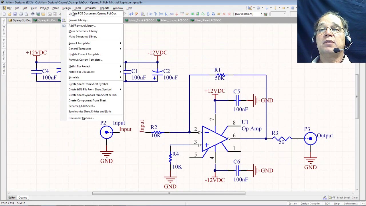
6 Updating the PCB from the schematic - YouTube

PCA9685-Wiring-Schematics-Diagram-Boards-Wiring-Guide-14core | 14core.com

Amana/Goodman Parts PCBDM133S DEFROST CONTROL BOARD-PCBDM133

Goodman Wiring Diagram Pcbdm133
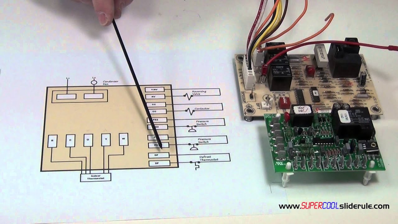
The Sequence of Operation for a Defrost Heat Pump Board - YouTube